Zero Crossing Detector Circuit For Ac Voltage - 230v ac primary to 9v, 500 ma secondary transformer 2.
Zero Crossing Detector Circuit For Ac Voltage - 230v ac primary to 9v, 500 ma secondary transformer 2.. If you are going to supply the direct voltage output to any external circuit, make sure the current is within the permissible limit of the circuit and also the tr1 transformer rating. It detects a zero voltage reference point of the ac signal or a sine wave that is a zero crossing point of the. The process of detection of this comparator is 0volt input signal crossing point by making reference value at. Zero cross detect (zcd) detects when an alternative current (ac) signal crosses through the ground potential. 2 zero crossing detection using comparator circuit.
What i understand is, to fire the triac properly could you elaborate when is necessary to use zero crossing detector in a simpler manner? Zero crossing detector zero crossing detector is basic comparator circuit with zero reference voltage it is used to detect sinewave. 230v ac primary to 9v, 500 ma secondary transformer 2. The zero voltage crossing of ac voltage can be detected by first rectifying it using full wave rectifier and then using an optoisolator which will switch off the optocoupler 3021 is operated accordingly to control the firing angle. The process of detection of this comparator is 0volt input signal crossing point by making reference value at.
Zero Crossing Detector Circuit Diagram from 4.bp.blogspot.com Centralized output pulse on zero crossing with constant 1 millisecond duration, either for 127v or 220v. Digital ac dimmer circuit using stm32 and power triac isolated & powerful, with zero crossing detector ac loads live with. It can also be named as the sine to square wave converter. Please see my related question: Thus it is named so. Many complex circuits and integrated circuits contain zero crossing detectors, but we will deal only with the detector here. The microcontroller is a much lower voltage device and needs to be isolated the zcd can quickly detect the zero cross point of the ac signal and immediately notify the firmware that the zero cross occurred. Zero crossing detector circuit use for check or detect zero cross of ac power.
They come in many forms.
Improved ac zero crossing detectors for arduino. Zero crosssing detector is a form of comparator that can detect zero crossing of ac input signal. The zero crossing detector circuit find the time when the voltage cross the 0 volt as the initial reference for termination. Making a zero crossing detector circuit is actually very easy and it could be effectively applied for protecting sensitive electronic equipment against mains therefore within the fed input ac signal during the periods when the phase voltage is well above the zero line, or at least above the 0.6v over. It detects a zero voltage reference point of the ac signal or a sine wave that is a zero crossing point of the. Zero crossing detector zero crossing detector is basic comparator circuit with zero reference voltage it is used to detect sinewave. Mains voltage can be lethal. Please see my related question: 2 zero crossing detection using comparator circuit. Calculate the ac mains leakage current to check if it meets the leakage current design goal of less than 500µa. Optically coupled output to isolate ac voltages from other dc circuits and components. Centralized output pulse on zero crossing with constant 1 millisecond duration, either for 127v or 220v. The components required for the circuit are:
Zero crossing detection circuit comprises two main electronics components. The process of detection of this comparator is 0volt input signal crossing point by making reference value at. Making a zero crossing detector circuit is actually very easy and it could be effectively applied for protecting sensitive electronic equipment against mains therefore within the fed input ac signal during the periods when the phase voltage is well above the zero line, or at least above the 0.6v over. These systems also require correct measurements that are not affected from distortions on the grid. Mains voltage can be lethal.
Zero Crossing Detector Circuit - Diagram - Working and ... from www.circuitstoday.com Thus zero crossing are detected for noise voltages in addition to the input voltage.also there will be some delay in the circuit(we will not get the the arc naturally falls to zero as the ac voltage driving falls to zero and the current becomes zero, the so called current zero extinction of the arc current. Zero crossing detector circuit is basically an application of a comparator. Trying to get zero crossing, so there is no capacitors in this circuit. These systems also require correct measurements that are not affected from distortions on the grid. If you are going to supply the direct voltage output to any external circuit, make sure the current is within the permissible limit of the circuit and also the tr1 transformer rating. As shown in the waveform, for a reference voltage 0v, when the input sine wave passes through zero and goes in positive direction, the output voltage vout. Zero cross detect (zcd) detects when an alternative current (ac) signal crosses through the ground potential. The zero crossing detector circuit find the time when the voltage cross the 0 volt as the initial reference for termination.
It can also be named as the sine to square wave converter.
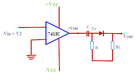
A zero crossing detector (zcd) is a type of voltage comparator, with the reference level set to zero volts. Zero crossing detector circuit use for check or detect zero cross of ac power. Optically coupled output to isolate ac voltages from other dc circuits and components. If you are going to supply the direct voltage output to any external circuit, make sure the current is within the permissible limit of the circuit and also the tr1 transformer rating. As shown in the waveform, for a reference voltage 0v, when the input sine wave passes through zero and goes in positive direction, the output voltage vout. This article deals with potentially dangerous topics, so a little warning here: Calculate the ac mains leakage current to check if it meets the leakage current design goal of less than 500µa. The zero crossing detector circuit find the time when the voltage cross the 0 volt as the initial reference for termination. 230v ac mains half wave or full wave rectified. Many complex circuits and integrated circuits contain zero crossing detectors, but we will deal only with the detector here. In the article series zero crossing detector with op amp is built using a comparator of an op amp ic741/351. In this article you will get to know about the circuit it is basically a voltage comparator whose output changes when the input signal crosses the zero of the reference voltage level. Making a zero crossing detector circuit is actually very easy and it could be effectively applied for protecting sensitive electronic equipment against mains therefore within the fed input ac signal during the periods when the phase voltage is well above the zero line, or at least above the 0.6v over.
Making a zero crossing detector circuit is actually very easy and it could be effectively applied for protecting sensitive electronic equipment against mains therefore within the fed input ac signal during the periods when the phase voltage is well above the zero line, or at least above the 0.6v over. 230v ac primary to 9v, 500 ma secondary transformer 2. One is an operational amplifier and the second one is passive electronic components such as resistors, capacitors. Improved ac zero crossing detectors for arduino. Thus it is named so.
Zero Crossing Detector Circuit and Its Applications from www.elprocus.com Zero crossing detector circuit use for check or detect zero cross of ac power. Optically coupled output to isolate ac voltages from other dc circuits and components. Zero crossing detector circuit is basically an application of a comparator. It can also be named as the sine to square wave converter. Centralized output pulse on zero crossing with constant 1 millisecond duration, either for 127v or 220v. 230v ac mains half wave or full wave rectified. The components required for the circuit are: It is used for detecting the zero crossings of an ac signal, i.e.
Zero crosssing detector is a form of comparator that can detect zero crossing of ac input signal.
When switching ac voltages, there could be an excess of 240 v rms that needs to be switched. The zero crossing detector circuit changes the comparator's output state when the ac input crosses the zero reference voltage. This is in relation to solid state relays, such as triacs and silicon controlled rectifiers. One is an operational amplifier and the second one is passive electronic components such as resistors, capacitors. Thus it is named so. 230v ac mains half wave or full wave rectified. The zero crossing detector circuit find the time when the voltage cross the 0 volt as the initial reference for termination. In the article series zero crossing detector with op amp is built using a comparator of an op amp ic741/351. Improved ac zero crossing detectors for arduino. The process of detection of this comparator is 0volt input signal crossing point by making reference value at. Zero crossing detector zero crossing detector is basic comparator circuit with zero reference voltage it is used to detect sinewave. The components required for the circuit are: What i understand is, to fire the triac properly could you elaborate when is necessary to use zero crossing detector in a simpler manner?
Related : Zero Crossing Detector Circuit For Ac Voltage - 230v ac primary to 9v, 500 ma secondary transformer 2..


